Asset Life-cycle Model, Asset Information Model, and Why BIM Won’t Work

The U.S. tried to foster BIM with NBIMS,  also others in the world tried PAS this and PAS that, and ISO this and ISO that… the issue remains that standards can’t replace knowledge and competency.

At the end of there day BIM represents nothing new relative to the efficient life-cycle management of the built environment.  Sure, software firms, and folks that love 3D and make a living from it will tell you otherwise, but the simple truth is that BIM, as we now know it, can not and will not survive.

The fact that BIM is a failure is sad because the world desperately needs to get a grip on how to manage its limited economic and environment resources and built structures are significant in that process.   Furthermore, there are critical life-safety and security issues associated with our crumbling and mismanaged physical infrastructure.

The primary issue is that many facility management and AEC professionals confused 3D visualization with asset life-cycle management.  While 3D visualization is nice tool, is is just that, an individual component in the toolbox.  It’s not even the most important tool.   Large, multi-site, multi-national real property portfolios can be efficiently managed WITHOUT 3D visualization and BIM software as now available.

Thus the pressure by countries, such as the UK to use BIM is misdirected.

Any government regulation should be directly solely at Owners.  More specifically, asset life-cycle management practices and collaborative construction delivery methods (integrated project delivery – IPD, job order contracting – JOC)  should be mandated.  This includes a formalized set up key performance indicators (KPIs), robust lean best management practices, and ongoing education and training.

The methods to eliminate the rampant environment and economic waste endemic to the Architecture, Engineering, Construction, Operations, and Owner sectors has been available for decades,  we simply don’t require Owners to do their jobs.

Owners must be required to develop technical and business competencies with respect to asset life-cycle modeling and total cost of ownership, and be able to LEAD collaborative teams of service providers.     Until this happens….   nothing will change, it is indeed as simple as that.

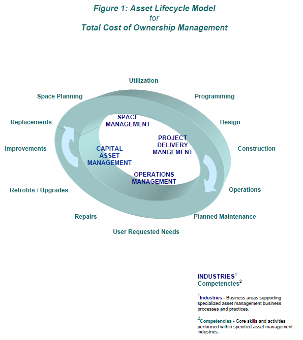
BIM asset life-cycle competencies

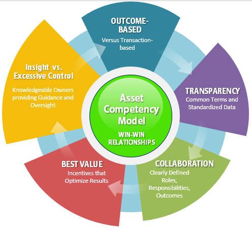
Asset Comptency Model

European Facility Management Data Standard – EN 15221 – 3

Common taxonomy is critical to productivity, transparency, collaboration, and information re-use/management.  Within the facility management where process, technology, and productivity lags, common taxonomy must be at the forefront.

Various standards are in place and evolving.  Here’s a quick view of FM data standards for Europe.

EN 15221-1: Facility Management – Part 1: Terms and Definitions  Version EN 15221-1:2006

This draft European standard gives relevant terms and definitions in the area of Facility Management. It also provides a structure of facility services.

EN 15221-2: Facility Management – Part 2:

Facility Management — Agreements -Guidance on how to prepare Facility Management agreements Version EN 15221-2:2006

This document is a working and standardized tool intended for parties who wish to draw up the Facility Management agreement within the European Common Market. It offers headings, which are not exhaustive. Parties may or may not include, exclude, modify and adapt these headings to their own contracts.

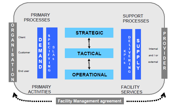
Definition of Facility Management – an integrated process to support and improve the effectiveness of the primary activities of an organization by the management and delivery of agreed support services for the appropriate environment that is needed to achieve its changing objectives.

FM Model


EN 15221-3: facility management – Part 3:

Guidance how to achieve/ensure quality in facility management

Provides guidance how to measure, achieve and improve quality in FM. It gives complementary guidelines to ISO 9000, ISO 9001 and EN 15221-2 within the framework of EN 15221-1.

Scope

Normative references

Terms and definitions

Basics of quality management

4.1      Importance of quality in FM

4.2      Criteria, background, elements and influences to quality

4.3      Type of characteristics

4.4      Pathway from needs to experiencing Delivery

4.5      Quality management

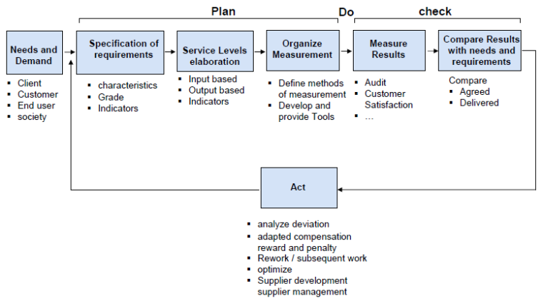
Process of quality management

5.1      General introduction of the process

5.2      Demand

5.3      Determining and defining requirements

5.4      Service Level (SL)

5.5      Developing measurement metrics (hierarchy of indicators)

5.6      Quality aspects by organizing delivery of fm products

5.7      Quality aspects by delivering fm products

5.8      General introduction into performance management

5.9      Measurement and calculation

5.10    Analyze deviation

5.11    Actions based on deviation

5.12    Continuous improvement

Quality:

degree to which a set of inherent characteristics fulfils requirements


Requirement:

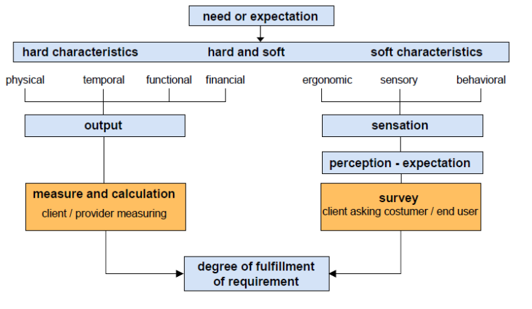
need or expectation that is stated, generally implied or obligatory

Characteristic: distinguishing feature

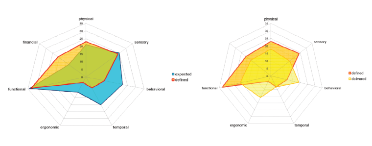
A characteristic can be inherent or assigned and can be qualitative or quantitative. There are various classes of characteristics, such as the following:

— physical (e.g. mechanical, electrical, chemical or biological characteristics);

— sensory (e.g. related to smell, touch, taste, sight, hearing);

— behavioral (e.g. courtesy, honesty, veracity);

— temporal (e.g. punctuality, reliability, availability);

— ergonomic (e.g. physiological characteristic, or related to human safety);

— functional (e.g. maximum speed of an aircraft).

Product:

result of a process

product categories, as follows:

– services (e.g. transport);

– software (e.g. computer program, dictionary);

– hardware (e.g. engine mechanical part);

grade

Category or rank given to different quality requirements for products, processes or systems having the same functional use.

service level

Complete description of requirements of a product, process or system with their characteristics.

The described set of characteristics in the SL can be graded within boundaries suitable for measurement and analysis.

indicator

Ceasured or calculated characteristic (or a set of characteristics) of a product according to a given formula, which assess the status or level of performance at defined time.

key performance indicator

Indicator that provides essential information about performance of the client´s organization.

The key performance indicators have to be given by the client´s organization, based on its strategic goals pursuing the development of the primary activities.

FM-indicator

Indicator that measures the quality of fm products.

They are used on different levels (e.g. strategic, tactical or operational Level).

FM-key performance indicator (fm kpi)

Indicator directly impacting the primary activities and the objectives of the client´s organisation.

Fm-indicator linked to client’s organisation objectives and related product which directly impacts the primary activities.

FM Need or Expectation
FM Process Overview
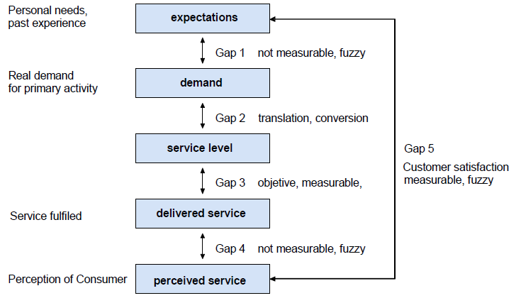
Gap Model
Gap Analysis

EN 15221-4: facility management – Part 4: Taxonomy of facility management

Focused on the concept of classified facility products / services by defining relevant interrelationship of service elements and their hierarchical structures, associated terms and cost allocation

EN 15221-5: facility management – Part 5:

Guidance on the development and improvement of processes

Provides guidance to FM organizations on the development and improvement of their processes to support the primary activities.

EN 15221-6: facility management – Part 6:

Space measurement

Area and space measurement for existing buildings


via http://www.4Click,s.com – premier software for cost estimating and efficient project delivery methods and management – JOC, SABER, IDIQ, IPD, SATOC, MATOC, MACC, POCA, BOA ….

BIM Standards – BIM Stratety and IFCs – Industry Foundation Classes


INTRODUCING A NEW METHODOLOGY TO DEVELOP THE INFORMATION DELIVERY MANUAL FOR AEC PROJECTS

Shiva (Vahideh) Aram, PhD Candidate,


shiva_aram@gatech.edu


Charles Eastman, Professor,


charles.eastman@coa.gatech.edu


Georgia Institute of Technology, Atlanta, USA

Rafael Sacks, Associate Professor,


cvsacks@tx.technion.ac.il


Technion – Israel Institute of Technology, ISRAEL

Ivan Panushev, Research Scientist,


ivan.panushev@gatech.edu


Manu Venugopal, PhD Candidate ,


manu.menon@gatech.edu


Georgia Institute of Technology, Atlanta, USA

ABSTRACT

The Industry Foundation Classes (IFC) create a neutral environment for interoperability by providing a comprehensive specification of the information throughout the AEC/FM project lifecycle, globally, across disciplines and software applications. However, the IFC schema does not capture the ways in which information is created and shared by practitioners; and the lack of specific definition of users’ exchange requirements has made it difficult to implement IFC compliant software solutions. The Information Delivery Manual (IDM) responds to these problems by proposing a methodology that captures business processes in AEC/FM projects and developing specifications of detailed user information exchange requirements. A progressive methodology to develop IDMs is presented in this paper. In this method Exchange Models (EMs) are utilized to provide the content of information exchange between users and/or software applications. Exchange Objects (EOs) are introduced as the fundamental elements in an exchange model, which contain the description of information units in non-technical terms that need to be exchanged in an exchange model. EOs are then developed further to provide the detailed technical attributes of the information categories in exchange models. EOs may be used in several exchange requirement definitions. Therefore, they are defined to be reusable within many exchange models. The level of detail and precision, and the representation type of EOs may vary in exchange models in different stages of the project lifecycle and are determined based on the business rules and with participation of industry experts. The details of the information capture to develop the IDM such that the IFC schema can be applied in national, local, or even project contexts are further illustrated. The paper finally presents the application of the introduced approach, using examples of architectural and structural precast concrete as a test base.

Keywords:


Industry Foundation Classes (IFC), Information Delivery Manual (IDM), Model View Definitions (MVDs), Interoperability, Building Information Modeling (BIM)

.

1. INTRODUCTION

The main objective of several national BIM efforts and standards is to improve the information technology comprehension and implementation in AEC/FM industry to transform industry supply chains through interoperable information exchange (NIBS 2008). The Industry Foundation Classes (IFC) define a neutral environment for interoperability by providing a comprehensive specification of the information throughout the AEC/FM project lifecycle, globally, across disciplines, and software applications. Interoperability enhancement

requires common understanding of industry processes and the information required for and resulting from executing these processes (Wix, Nisbet, and Liebich 2009).

However, the IFC schema does not capture the ways in which information is created and shared by practitioners. Implementation of IFC compliant software solutions is hampered by the lack of specific exchange requirement definitions by users. This paper is inspired by the PCI NBIMS project that aims at implementing IFC based interoperability solution for architectural and structural precast concrete. The project team’s role was to technically facilitate the precast concrete information exchange standard development. Based on this project a National BIM Standard, for precast concrete design, engineering, fabrication, and erection, was developed (Eastman et al. 2010a).

IFC based information sharing tools need to be capable of securely and reliably exchanging accurate and appropriate data for specific purposes. To achieve this goal the first step is to capture the deployment information of exchange requirements. Then, one must develop an IFC based technical solution to satisfactorily meet those requirements and finally, it is necessary to deploy the technical solution (Hietanen 2006).

Usually each IFC implementation and development project focuses on a small subset of the IFC schema based on the user oriented “use cases”. Usually use case definitions are the first step of model specifications and are developed on the basis of business processes and related Exchange Requirements (ER) based on the value chain of the end user (Weise, Liebech, and Wix 2009). This process is accomplished through a progressive method to develop Information Delivery Manual (IDM), presented in this paper. In this method, Exchange Models (EMs) are utilized to provide the content of information exchanges between users and/or software applications. Then Exchange Objects (EOs) are introduced as the fundamental reusable elements in an exchange model, which contain the descriptions of information units that need to be exchanged in non-technical terms in an exchange model.

In this paper, we focus on the user requirements stage, as defined in the IDM. In the next step and through IFC Model View Definitions (MVDs), subsets of the IFC Model Specification required for IFC implementation of exchange models in software applications are defined. Therefore, MVD development efforts aim to providing an unambiguous guidance for implementation of IFC as a technical solution for interoperability needs in specific use cases.

2. INFORMATION DELIVERY MANUAL (IDM)

To facilitate interoperability in the AEC/FM industry, product data standards like IFC and CIS/2 have been developed. The IFC model specification is the most comprehensive data model with an object oriented data-schema that provides support for collecting data from a project model in a neutral computer language and representing shared information in a wide range of AEC/FM industry processes (Froese et al. 1999). The data sets’ definitions and rules embedded in the IFC data model provide the basis for developing IFC interfaces for software platforms, which enable sharing data between software applications with different internal data structures (NIBS 2008).

IFC implementations enable users to access the highly structured and attributed object model data used in Building Information Modeling using an application programming interface (API) according to their predefined rights. However, the IFC schema does not define the information exchange requirements specific to different project stages and between different project actors and software applications, which makes it difficult to develop useful IFC software interfaces. Accordingly, software developers and users demand IFC implementation guidelines that allow focusing on use cases of interest and guarantee compatibility with other software implementations. Development of the IDMs and MVDs has been a significant initiative to solve this problem by identifying the subset of IFC data model needed to support the user defined business processes (Wix, Nisbet, and Liebich 2009).

The main purpose of developing IDM and MVD is to define the specifications for mapping the information exchange with the IFC model objects for implementation in software interfaces. Then business rules are defined for these business processes. IFC implementation mainly includes deciding about use cases that should be supported in a specific project and thus needs substantial knowledge about the BIM tools that shall be used in the

projects and their current IFC capabilities (Bazjanac 2002). IFC development efforts incorporate requirements defined by industry experts.

The IDM framework that we have incorporated in this project is different in some aspects from some European efforts. The IDM guide developed by buildingSMART, Norway (BuildingSMART 2006) and some other European IFC deployment guides have expanded the scope of IDM to all the IFC deployment activities from defining process maps to developing IFC concept bindings. So the boundary between IDM and MVD development is blurred. On the other hand, some IFC deployment guides (Hietanen 2006) have considered the distinction between these two. The second approach views IDM as a method to identify the user exchange requirements during different processes with specific purposes. And the task of mapping these information exchange requirements with particular IFC releases is passed to MVD development stage. This approach clarifies the interface between IDM and MVD and makes it simpler to apply the whole IDM/MVD methodology. It provides a more effective way to communicate the exchange requirements to industry experts at the IDM level and to software developers at the MVD level.

Considering all these advantages, we have applied the latter methodology in the current project, distinguishing the scope, purpose, and outcome of IDM and MVD development processes. Thereby, IDM is applied exclusively as an information exchange requirement definition process and MVD as an IFC based technical solutions development process. Therefore, the final outcome of an IDM is a set of IFC independent information items defined for different Exchange Models (EM). Each of these information items, which are called Exchange Objects (EOs), can then be reused in several EMs and their functionality in each EM is illustrated by specified business rules and level of detail.

2.1.Process Maps

Facilitating the integration and collaboration between different disciplines involved in an AEC/FM project is one of the major focuses of BIM. In fact there is a close interaction between the BIM value proposition in projects and degree of workflow integration and continuity of information flow through project lifecycle. Hence, BIM aims to eliminate the non-value adding or lower value adding activities, to integrate the high value adding but fragmented tasks and to improve the automation of processes and the project performance in terms of project time and cost. To achieve these goals the first step is to determine the information value chain throughout projects and identify the inefficiencies of current practices. This will enable an enterprise systems analysis and devising alternative processes that streamline the information exchanges and enhance the information value gained by different project activities. The processes, actors, and information flow that are aimed to be supported by BIM tools are defined by Process Maps (PM) (Weise, Liebech, and Wix 2009).

The Business Process Modeling Notation (BPMN) is a standard for expressing process maps which are flow-oriented representations of business operations (Ouyang et al. 2009). In BPMN, developed by Object Management Group (OMG), the useful ideas of previous process modeling notations like IDEF0 (ISO10303) and the activity diagrams component of the Unified Modeling Notation (UML) have been incorporated (OMG 2005). BPMN models have been mainly used to facilitate information exchange and communication between project participants and to aid with decision-making based on various analysis techniques. However, detailed BPMN models are increasingly used as maps to identify the information packages exchanged in business processes and so to define required software features in systems development efforts (Ouyang et al. 2009).

The main components of process models developed by using BPMN are (i) flow objects, representing activities, decision-making gateways, or business events which differentiate different triggers or results, and (ii) connecting objects capturing either the message flow between activities that are carried out as a result of activities or the logical sequence of activities (OMG 2005). BPMN uses swimlanes to categorize activities with different functional objectives or capabilities (White 2004). Some swimlanes contain the exchange requirements of a data source that may be carried either by a BIM tool in the form of a model – called Exchange Models (EMs) in our method – or other non-BIM forms of information exchange, for example, informal comments on the architectural design by structural engineer. Exchange Models (EMs) are utilized to provide the content of information exchanges between users and/or software applications. Further, in order to provide appropriate level of detail,

tasks may be broken down into sub-processes that may be executed multiple times concurrently (Weise, Liebech, and Wix 2009).

In the PCI NBIMS project, that we are going to discuss in this paper, mapping processes using BPMN was the first step in developing an Information Delivery Manual (IDM). BPMN models were useful for identifying the Exchange Models (EMs) in precast concrete projects and provide a base to later identify the content of each information exchange package in the IDM.

A Use Case

Figure 1: Example of BPMN and a use case

2.2.Use Case Approach

The main building blocks of process maps are called “use cases”. They define information exchanges between any two actors in a project aimed at achieving a specific goal, within a specified phase of a project’s lifecycle. Hence, use cases provide detailed description of the content of the information exchanges. Defining use cases is the first step of determining model specifications, and thereby needs special attention in IFC based software interface development efforts.

A particular use case can depict a singular information exchange or a set of iterated exchanges that are illustrated by a loop sign as shown in Figure 1. Use cases are usually part of a greater network of information exchanges and collaborations throughout the project stages and between different project actors that provide the comprehensive process maps of a project (Eastman et al, 2010b).

Developing and implementing standardized information exchanges across industry domains can support vigorous data sharing throughout the information value chains of the industry. While interoperability tools like IFC are international mechanisms to share data, the required data to be shared is different in various localities (NIBS 2008). Defining the content of the information exchanges for each use case, known as Exchange Requirements, is a process based on the involvement of industry experts. This way Exchange Requirements reflect the local processes and legal and contractual obligations. Therefore, it is important that internationally applicable solutions strongly support the specific local applications (Hietanen 2006). Moreover, business requirements should be defined in a way that demand improvements in the status quo and aim to optimize current information sharing thereby initiating further IFC developments (Weise, Liebech, and Wix 2009).

Because of the diverse localities and need for customization of business processes, there is no single process map structure that can represent the entire AEC/FM industry spectrum. Usually there are various ways to compose use cases to achieve similar final purposes (Eastman et al, 2010b). However, some use cases may not be implemented in specific sub-domains of the industry or new use cases may be added for specific purposes.

Therefore, in designing the IDM it is important to identify the best practices across the industry and focus efforts on developing interoperability tools that support (and possibly advance) these best practices.

2.3.Exchange Models

The result of the process modeling stage is the definition of a set of exchanges needed to support some business activity or domain, characterized by one or a set of use cases between two actors or roles and different stages in the project delivery lifecycle. The next step after identifying the use-cases is to define the information exchange content. As with developing the BPMN, the active involvement of industry experts is necessary in defining the sets of information required for each exchange.

Over multiple iterations, working on two different domains, we have tentatively developed a template to capture the information needed to support the user specification of an information exchange. The exchange model content template and an example are provided in Figure 2 and 3.

Figure 2: Exchange model content template (Eastman et al. 2009)

Project Stage

What is the Omniclass design stage?


Exchange Disciplines


Who are the parties to this exchange?

By Omniclass discipline number and name?

(can be >2 disciplines, but using the same basic data.)


Description


Verbal description of:

1. The purpose of the exchange

2. The required contents of the exchange

3. The optional contents of the exchange

4. Example software in the exchange

5. Whether the exchanges are round trip or one-way

Related Exchange Models


Other exchanges this one interacts with (proceeding and succeeding exchanges)


via www.4clicks.com – Premier cost estimating and project management software for JOC, IPD, SABER, SATOC, MATOC, MACC, IDIQ, POCA, BOA.
NIBS Recommends that Congress Prioritize Building Industry Concerns

While “Government Focus” and/or “Government Priority” may seem to oxymorons to many of us, it is indeed past due that the Federal Government address Sustainability and Productivity issues within the building / AEC sector.

Efficent Construction Delivery Methods - Sustainabilty - Climate Change

The altered economic landscape and the ever ticking global climate change clock require that we address facility renovation, repair, and sustainability immediately.  This will require consistent condition assessment practices and efficient project prioritization mechanisms as well as efficient construction delivery methods such as Integrated Project Delivery (IPD) and Job Order Contracting (JOC).

 May 26, 2011

National Institute of Building Sciences, Leading Organizations Issue Report of Findings

A new report from the National Institute of Building Sciences Consultative Council identifies five primary areas of concern regarding the nation’s buildings and infrastructure, and provides recommendations for action. Topics include: Defining High-Performance and Common Metrics; Energy and Water Efficiency; Codes and Standards Adoption and Enforcement; Sustainability; and Education and Training.

Time for Building Standards and Efficient Project Delivery

The National Institute of Building Sciences enabling legislation established the Consultative Council as an important link among disciplines in the field of building technology. The Council engages the leadership of key organizations with the intent of providing findings and recommendations for the advancement of the built environment. The Council report represents the collective vision of these leading organizations from across the building community.

“Given the many services we ask our buildings and infrastructure to perform, it is essential that the many disciplines and organizations responsible for the design, construction, operations and maintenance of buildings work together to identify overarching needs that can lead to widespread high-performance buildings,” said Ryan Colker, Director of the Consultative Council and Presidential Advisor at the Institute. “The Council’s initial report reflects this collective thinking and has the potential to significantly influence policymakers and the building community.”

The Council recommendations identify cross-cutting issues essential for reaching building industry goals. Specific recommendations include:
o The need to establish common definitions to guide measurement and expression of actual performance;
o Energy codes and standards should shift from prescriptive requirements towards performance-based provisions aimed at ultimately achieving net-zero energy use;
o Investment in energy and water related infrastructure is desperately needed and will vastly improve efficiencies and create jobs;
o Increased participation by federal, state and local government agencies would yield more uniformity and consistently adopted and understood codes, and increase the effectiveness of model building codes;
o At the state and local level, financial and technical resources must be available to ensure code and standard requirements are followed;
o Achieving sustainability requires addressing the triple bottom line of economic growth, environmental stewardship and social progress in all building and infrastructure projects;
o Public construction should address life-cycle costs and benefits, while accounting, financing, insurance and tax policies should facilitate and promote private investments in sustainable buildings and infrastructure;
o Education and training should be aimed at facilitating the entire life-cycle of buildings, from concept to design, construction, commissioning, occupancy, modification/renovation, and deconstruction; and
o Education and training incentive programs should be available to cover all levels and types of businesses and organizations, and should encompass all design, construction, maintenance and operational core competencies.

In 2010, Consultative Council members included: ASTM International; American Institute of Architects; American Society of Civil Engineers; American Society of Heating, Refrigerating and Air-Conditioning Engineers; Associated General Contractors of America; Building Owners and Managers Association, International; Construction Specifications Institute; ESCO Institute; Extruded Polystyrene Foam Association; Illuminating Engineering Society; International Association of Plumbing and Mechanical Officials; International Code Council; National Insulation Association; National Opinion Research Center at the University of Chicago; and United Association of Journeymen and Apprentices of the Plumbing and Pipefitting Industry. Joining the Council in 2011 are the Laborers’ International Union of North America and HOK. The summary of recommendations appears in the Institute’s 2010 Annual Report, which is sent to the President of the United States and the U.S. Congress. To download a copy of the complete Consultative Council report, visit www.nibs.org/cc/Activities.

About the National Institute of the Building Sciences
The National Institute of Building Sciences, authorized by public law 93-383 in 1974, is a nonprofit, nongovernmental organization that brings together representatives of government, the professions, industry, labor and consumer interests to identify and resolve building process and facility performance problems. The Institute serves as an authoritative source of advice for both the private and public sectors with respect to the use of building science and technology. For more information, please visit www.nibs.org.

What is BIM – Software, Business Process? – BIM Definition – NIBS – National BIM Standard – BIM Standards

Both….  BIM is a digital technology and a business process for life-cycle facility management, from concept thru disposal.

The below figure represents components of a BIM strategy.

What is a BIM?

The National Building Information Model Standard Project Committee defines BIM as:

Building Information Modeling (BIM) is a digital representation of physical and functional characteristics of a facility.  A BIM is a shared knowledge resource for information about a facility forming a reliable basis for decisions during its life-cycle; defined as existing from earliest conception to demolition.

A basic premise of BIM is collaboration by different stakeholders at different phases of the life cycle of a facility to insert, extract, update or modify information in the BIM to support and reflect the roles of that stakeholder.

The US National BIM Standard will promote the business requirements that BIM and BIM interchanges are based on:

  • a shared digital representation,
  • that the information contained in the model be interoperable (i.e.: allow computer to computer exchanges), and
  • the exchange be based on open standards,
  • the requirements for exchange must be capable of defining in contract language.

As a practical matter, BIM represents many things depending on one’s perspective:

  • Applied to a project, BIM represents Information management—data contributed to and shared by all project participants.  The right information to the right person at the right time.
  • To project participants, BIM represents an interoperable process for project delivery—defining how individual teams work and how many teams work together to conceive, design, build & operate a facility.
  • To the design team, BIM represents integrated design—leveraging technology solutions, encouraging creativity, providing more feedback, empowering a team.¹

NBIM standard will incorporate several elements described later in this document but the focus will be on standardized processes which define “business views” of data needed to accomplish a particular set of functions.

Why BIM should be renamed BIMM – The Value of BIM

BIM should should have been can BIMM – Building Information Modeling and Management. The emphasis upon 3D is silly, and the focus upon 3D replacing 2D is equally misdirected.

Products like Revit and Archicad are only relatively small components of a BIM solution.  BIM is a process embedded within and support by digital technology that enables more efficient cradle-to-grave management of the built environment.

Owners, contractors, A/E’s, oversight groups, and communities will all benefit from BIM relative to the management and usage of the built environment.

As many say, the “I” in BIM is the critical aspect.  Defensible, accessible, transparent, accurate and re-usable information is the true value of BIM.

What is BIM?

What is BIM?

BIM Definition

(  Source: BSI via http://www.4clicks.com )

BIM is the process of generating and managing information about a building during its entire life cycle. BIM is a suite of technologies and processes that integrate to form the ‘system’ at the heart of which is a component-based 3D representation of each building element. This replaces traditional design tools currently in use.

Each component is generated from a product library and has embedded information about the product and its placement, material, specification, fire rating, U-value, fittings, finishes, costs, ‘carbon content’ and any special requirements, which is stored in the system.

Key Benefits of BIM:

  • Early cost certainty
  • Reduced delivery costs
  • Reduced operational costs
  • Green performance
  • Reduced risk
  • Predictable planning.

Who should use BIM?

BIM is for firms in all parts of the architectural, engineering and construction industry, whatever their sizes, as well as clients who may be planning to require their supply chain to use BIM tools.

It is especially useful for:

  • Contractors
  • Architects
  • Designers
  • Structural engineers
  • Building Services Engineers
  • Cost consultants
  • Manufacturers
  • Clients.

BIM Deployment Plan from Revit / Autodesk

BIM Strategy

The Autodesk BIM Deployment Plan – tools and guidance for building industry professionals interested in implementing Building Information Modeling (BIM) – is a reasonable framework for those beginning to investigate BIM, however, it lacks requisite depth relative to 4d, 5d BIM as well as contruction delivery methodology.  

A comprehensive BIM strategy from an owner perspective (and, in my opinion contractor and A/E’s as well as other stakeholders), should include capital planning and management (lifecycle costing, capital renewal, physical/functional conditions management), operations and maintenance (repair, maintenance, minor renovations-preventive, routine, maintenace), space planning/management, and integration of efficient construction devlivery methodsy (JOC – Job Order Contracting for facility repair/maintenance, IPD – Integrated Project Delivery for new construction, etc.), and associated reference cost data, standard definitions/metrics/taxonomy, ….

Tools offered in the Autodesk BIM deploym,ent plan are intended to provide a practical framework for AEC stakeholders, and can be used by individual organizations on specific projects. The BIM Deployment Plan includes:

  • BIM support materials for owners, architects, engineers, and contractors
  • Templates to streamline multi-discipline communications
  • Recommendations for roles and responsibilities
  • Best business process examples
  • Software suggestions for an effective BIM environment

BIM_Deployment_Plan_Final

Definitions of Terms Used in This Document
 

As-Built Model Model

—The final model that shows how a building was actually delivered and assembled. Sometimes referred to as the Record Model.

Building Information Modeling (BIM)—An integrated process aimed at providing coordinated, reliable information about a building project throughout different project phases—from design through construction and into operations.  BIM gives architects, engineers, builders, and owners a clear overall vision of the project—to help them make better decisions faster, improve quality, and increase profitability of the project. 
 
Clash Detection — The process of checking for clashes and interferences in the design of one or more BIM models.


Collaborative Project Management — A software solution that enables effective management of and collaboration on all project related communication, information, and business processes across the plan, build, and operate phases of the building lifecycle. The most common processes include collaborative documentation, design, bid, construction, cost, and operations management.  (Examples of software include www.4clicks.com Project Estimator for JOC construction delivery).     Coordination Model—A model created from two or more models, used to show the relationship of multiple building disciplines such as architectural, civil, structural, and MEP (mechanical, electrical, and plumbing).

Core Collaboration Team —The group of people – which should include someone from each party working on the project, such as the owner, architect, contractor, subconsultants, suppliers, and trade contractors—responsible for completing a BIM Deployment Plan, creating the document management file folder structure and permission levels in the collaborative project management system, and enforcing the action plan set out in that document throughout design and construction of the project.
Design Intent Model —The model used to communicate the design intent of a building.
Industry Foundation Classes (IFC) —A neutral and open file format structure developed by the International Alliance for Interoperability (IAI) to enable interoperability between modeling software systems.
Integrated Project Delivery (IPD)—A project delivery process (similar to JOC for facility repair, renovation, and sustainabilty)  that integrates people, systems, business structures, and practices to collaboratively harness the talents and insights of all participants in order to optimize project results, increase value to the owner, reduce waste, and maximize efficiency throughout all phases of design, fabrication, and construction (AIA,  Integrated Project Delivery: A Guide , 2007, available at http://www.aia.org/ipdg).
Model Integrator—A tool used to combine and/or link design files from different software platforms.
Model Manager(s)—The project team member(s) responsible for managing the collaboration and sharing of electronic files during the project. Model managers are also responsible for maintaining the integrity of BIM models, which can include gathering, linking, and uploading updated models.
Parametric —The relationships among and between all elements of a model that enable coordination and change management. These relationships are created either automatically by the software or manually by users as they work.
Project System Administrator (PSA) —The person who administers, and sets up folders for, the collaborative project management system. Responsible for managing and creating new user accounts, as well as contact and company information. 

MasterFormat / MasterFormat2004 Changes

MasterFormat® Updates:
Did you know CSI and CSC have a new annual revision cycle?
Did you know there is a new Division?
The major updates to MasterFormat2004 are:

  • A new division, Division 46 – Water and Wastewater Equipment, which significantly expands the document’s coverage of environmental engineering specifications
  • Revisions to Division 44 – Pollution and Waste Control Equipment, so that it complements the addition of the new Division 46
  • New specifications related to polished concrete (Division 03)

CSI and CSC designed the 50-division format of MasterFormat 2004 so that it can accommodate additional divisions and changes as the industry evolves. The 50-division format is now used in a majority of commercial projects in North America.
The MasterFormat revision process is conducted by the MasterFormat Maintenance Task Team (MFMTT), a committee of volunteers appointed by CSI, CSC and MasterFormat Sponsors (ARCAT, ARCOM, Building Systems Design, Inc., the Construction Sciences Research Foundation, Inc., McGraw-Hill Construction, and Reed Construction Data).

4d 5d BIM and COBIE – What you should know?

Some government agencies, such as the Veterans Administration (VA) now require the use of COBIE.

VA has adopted COBIE as the methodology to electronically transfer building information after construction is complete for facilities management. The COBIE spreadsheet (see COBIE2 Template) is part of the U.S. National Building Information Model Standard (NBIMS).

Third-party utilities facilitate the automatic creation and transfer of some data between BIM and a COBIE spreadsheet via IFC files as an intermediate stage, and some BIM software may include creation of and data transfer to the spreadsheet directly without making use of intermediate IFC files.

Where possible, automatic means should be used to create and fill in the COBIE spreadsheet.

The Design/Construction Team shall consult their BIM software vendor(s) for the most current COBIE utilities. However, the completed COBIE worksheets will also contain some information that is entered manually into the electric file, either because the information currently cannot be conveniently extracted from the BIM or because it does not reside in the BIM.

The Design/Construction Team is encouraged to provide as much information in COBIE as is known at the time of the deliverable. The required worksheets in COBIE will be filled out in step with the LoD and Design Phases (see Object Element Matrix).

The Design/Construction Team(s) shall submit the most current version of the COBIE spreadsheet with other required deliverables at each Project Phase.

With CD deliverables, the COBIE-4- Type and Component worksheets are required. These fields provide component Name, Description, and Creation Date. The medical equipment listed in the VA-SEPS-PFD export shall be noted on the COBIE spreadsheet.

VA also requires sustainability related testing.

Virtual Testing and Balancing

The VA requires virtual testing and balancing of the architectural model to support sustainable building systems design and analysis. Room data can be read from the linked architectural model to create mechanical spaces (each space is the same as the room in the architectural model). Multiple spaces are joined to create zones. This data can used to calculate native heating and cooling analysis that is built into the MEP software or exported using gbXML to an external analysis application such as eQuest, Trane/Trace, or DOE based analysis programs. AEs can then bring this data back within the model to check their work. One of the methods is to create a Space/Room schedule that will show calculated air flow vs actual air flow. See figure below. All air flows can be checked for load balance to the terminal box and all the way back to the air handling units. Check with MEP modeling software companies for additional information.

Space Airflow Schedule

-1- Additional space engineering criteria will be added over time.

-2- With the exception of “Army_Cat,” “Navy_Cat,” and “USAF_Cat,” which can be removed.

-3- Mechanical, Electrical, Plumbing, Fire protection (MEPF)

-4- www.wbdg.org/pdfs/cobie_spreadsheet.pdf

-5- Generally this is weekly

-6- Fixtures, Furniture, & Equipment (FFE)

BIM Applications

At a minimum, BIM shall be used for the following applications:

7.1 Space and Medical Equipment Validation

VA-SEPS Data Required in BIM: VA uses the Space and Equipment Planning System (VA-SEPS), which is a data based planning tool shared by the VA, U.S. Navy, Army, and Air Force to create a Program for Design (PFD). Information regarding medical need requirements is entered to generate the space requirements and medical equipment associated with that space for a particular project. The output of VA-SEPS is a PFD containing a list of rooms (spaces) and medical equipment, with their identifying computer codes used to associate and track this information through design and construction.-1- Some of these codes will ultimately be imported into the facility management software to provide VA with the ability to manage, track, and report on VA’s spatial inventory, medical equipment, and building equipment. In addition, the BIM software will automatically assign a unique GUID to spaces which will identify each individual space.

The BIM is required to capture this space and equipment data in the BIM model. All BIM modeling must preserve the field name designations and text values found in the VA-SEPS BIM export files.-2- To do this, the final PFD for each project must be electronically exported from the VA-SEPS database for import and reuse in BIM. A spreadsheet export can be obtained in VA-SEPS by going to the Selection Tree and clicking on Select a Project, then choosing the proper project. Then on the sub-menu, select Export Project Data to BIM. This will create a MS Excel file with the associated data codes, which can then be imported into the BIM software’s “space” tool and equipment data into “elements” or “objects” tools appropriate to the particular BIM software, or the data can be linked in a database external to the BIM software. Medical spaces and medical equipment shall be derived from the model and validated against the PFD electronically at each submittal stage.

Note that if the original PFD was not developed using VA-SEPS or if new spaces are added during the design process, then a new VA-SEPS-PFD export must be created to obtain the proper codes.

7.2 Architecture—Spatial and Material Design Models

The timing of the Level of Development (LoD) required for elements(s) or systems(s) will be dependent entirely upon the project execution strategy used for the project, as the deliverables and their timing will be different for DBB than for DB or IDP.

The Object Element Matrix shows the evolution of the architectural spatial model as it is refined during the design process as the project progresses toward construction. As materials and components are selected, generic assemblies shall be assigned material properties, sizes, sustainability credits tracked, and other specific component information defined to clearly identify building features such as walls, floors, roofs, doors, and windows. The program space requirements shall be modeled in the spatial model and validated electronically against the PFD at each stage of the project and submitted with the required deliverables.

7.3 Energy Analysis

Energy simulation and life-cycle cost calculations shall be based on information extracted directly from BIM and validated by energy modeling. The models shall be created to a Level of Development (LoD) and quality as required to perform an energy analysis appropriate for the phase and decision requirements of the project. When internal spaces are defined, they shall be modeled with internal environment parameters for early MEP design.

Design Teams shall utilize energy modeling and sustainable design software that extracts BIM data to the appropriate file format for the analysis tool.

7.4 Design Visualization for Communication, Functional Analysis, and Constructability

BIM provides the opportunity to build a virtual building and to virtually test that building for functionality during design. This allows project stakeholders to see and understand design solutions that represents reality so they can work towards improving the building design before construction starts. VA is open to innovation and encourages the Design Team to find efficiencies and uses for BIM to enhance communication for the project. At a minimum, the model shall be integrated into design reviews, review submittals, and 3D construction documentation views. Areas that would benefit from the use of 3D imagery and fly-throughs during the design process and during construction shall be identifed and noted in the BMP(s).

Visualization tools refer to animations, fly-throughs, static 3D renderings, 4D process sequencing, and other techniques to assist decisionmaking and comprehension. It should be noted that even though the BIMs contain most of the source information needed for visualization, they may require further refinement in specific animation and visualization software to accomplish the intended results.

During design, special consideration must be given to medical staff and maintenance issues. At a minimum, BIM shall be used to validate:

  • Nurses’ walking distances
  • Nurse-station sightlines
  • Process areas where timing and volume may be problemmatic (such as patient queuing for waiting rooms and pharmacy, pharmacy delivery routes/timing
  • Supply, Processing, & Distribution (SPD)
  • Animations/graphics showing major building equipment and medical equipment space clearance reservations for operations, repair, maintenance, replacement
  • Color coding of floorplates for determining medical room/department locations and square footages, and circulation
  • Constructability

The Design and ConstructionTeams are encouraged to explore options to use the BIM and other electronic tools to enhance the project quality and delivery times, including quantity take-offs, cost estimating, overall project scheduling, subcontractor coordination and manpower loading, off-site fabrication, and other widely discussed BIM benefits.

7.5 Building System Models—Structural, MEPF,-3- and Interiors

Structural, MEPF, and interior design information is required to be developed in BIM.

7.6 Masterplan Space Scheduling and Sequencing—4D

For design work that includes sequencing of renovation swing space or masterplanning for long-term build-out, BIM 4D shall be used to illustrate the phasing plan to interact, communicate, and get approval of the final design and spatial sequencing with the medical staff.

7.7 Communication of Construction Scheduling and Sequencing—4D

The Contractor shall link BIM to the project schedule as a communication method to coordinate with the Medical Center and the VA Resident Engineer logistics that affect medical center operations or require shutdown of any affected facilities and utilities. The animated phasing plan shall address such issues as swing space during construction, parking interruptions, and re-routing of pedestrian/vehicular traffic, or any other construction work that could affect Medical Center operations.

It is recommended that the Contractor also use BIM – 4D in schedule planning and communication with the subcontractors and to understand the impact to the construction schedule of other changes during the duration of the project.

7.8 COBIE/Commissioning

VA has adopted COBIE as the methodology to electronically transfer building information after construction is complete for facilities management. The COBIE spreadsheet (see COBIE2 Template) is part of the U.S. National Building Information Model Standard (NBIMS). Third-party utilities facilitate the automatic creation and transfer of some data between BIM and a COBIE spreadsheet via IFC files as an intermediate stage, and some BIM software may include creation of and data transfer to the spreadsheet directly without making use of intermediate IFC files. Where possible, automatic means should be used to create and fill in the COBIE spreadsheet.

The Design/Construction Team shall consult their BIM software vendor(s) for the most current COBIE utilities. However, the completed COBIE worksheets will also contain some information that is entered manually into the electric file, either because the information currently cannot be conveniently extracted from the BIM or because it does not reside in the BIM.

The Design/Construction Team is encouraged to provide as much information in COBIE as is known at the time of the deliverable. The required worksheets in COBIE will be filled out in step with the LoD and Design Phases (see Object Element Matrix).

  • The Design/Construction Team(s) shall submit the most current version of the COBIE spreadsheet with other required deliverables at each Project Phase.
  • With CD deliverables, the COBIE-4- Type and Component worksheets are required. These fields provide component Name, Description, and Creation Date. The medical equipment listed in the VA-SEPS-PFD export shall be noted on the COBIE spreadsheet.

7.9 Clash Detection/Coordination

General

  • It is the Design/Construction Team’s responsibility to conduct and manage an adequate and thorough Clash Detection process so that all major interferences between building components will have been detected and resolved before construction. It shall the goal of the Design/Construction Teams to reduce the number of changes during construction due to major building interferences to zero.
  • The BIM Manager shall assemble a composite model from all of the model parts of each design discipline for the purpose of performing a visual check of the building design for spatial and system coordination. Vertical shafts should also be reviewed to ensure that adequate space has been allocated for all of the vertical mechanical systems and that all of the shafts line up floor to floor. Prior to each scheduled coordination meeting, an updated clash report will be issued by the BIM Manager to the technical discipline consultants.
  • On a multistory project, the models may need to be split on a level-by-level basis for MEPF coordination. If a floor is particularly large, it may also need to be split by zones to reduce file size. Typically, 3D clash detection/coordination continues on a single floor until building systems are fully coordinated, and then continues on the next floor up.
  • Coordination software shall be used for assembling the various design models to electronically identify, collectively coordinate resolutions, and track and publish interference reports between all disciplines. The technical disciplines shall be responsible for updating their models to reflect the coordinated resolution.
  • The team shall review the model and the Clash Reports in coordination meetings on a regular as-needed-5- basis throughout the design phases until all spatial and system coordination issues have been resolved.
  • During the construction phase, the accuracy of fabrication models shall be verified. Prior to each fabrication submittal for approval, fabrication contractors shall submit their models to the Contractor’s BIM Manager for integration and clash detection/coordination and resolution.
  • Internal Clash Resolution – Design Consultants and Subcontractors who are responsible for multiple scopes of work are expected to coordinate the clashes between those scopes prior to providing those models to the BIM Manager for spatial and system coordination.
  • Spatial Coordination Verification: Verification and tracking of resolved conflicts of all trade coordination issues which could result in change orders or field conflicts shall be provided to VA during project milestone dates, and should be fully resolved before bidding.
  • For ease of identification during the 3D Clash Detection/Coordination process, it is recommended that the following trades be represented in these assigned colors:

Trade colors for Clash Detection

Architecture: White
Structural Steel: Maroon
Concrete: Gray
HVAC Equipment: Gold
HVAC Supply Duct/Diffuser: Blue
HVAC Return Duct/Diffuser: Magenta
HVAC Pipe: Gold
Electrical Equipment: Dark Yellow
Electrical Conduits: Light Yellow
Communication Conduit: Light Blue
Electrical Cable Tray: Dark Orange
Electrical Lighting: Yellow
Plumbing Water: Cyan
Plumbing Sewer: Magenta
Plumbing Storm Drain: Green
Fire Protection: Red
Pneumatic Tube: Dark Green
Equipment (Medical): Light Green
Medical Gas: Light Green
Security Systems: Orange
Fire Alarm: Fuchsia.

Minimum Requirements for Spatial Coordination and Clash Detection

  1. Architecture + Structural: Below-grade spaces, proposed floor plates with major penetrations, floor-to-floor heights, beam clearances, heavy utilities locations, floor loads, core, and vertical shafts, beam depths and required clearances, patient lift mechanisms, slab thickness, columns, column caps, and seismic bracing. Provide adequate space for construction and maintenance access to structural elements, building equipment, and distribution systems.
  2. Architecture + MEPF: Structural and space elements, flow and isolation requirements, proposed functional area configurations, floor-to-floor heights, fire containment, vertical and horizontal transportation. Possible future expansions shall be considered and shall be clash-free.
  3. MEPF/HVAC + Architecture, Structure, and Telecommunications: Main distribution and collection systems, configurations and sizes for piping, duct, conduit, power wiring, blowers; diffusers; intakes, large compressors. Clearance reservations for equipment maintenance filter removal, and equipment removal and replacement shall be modeled with the equipment, and sign-off on the adequacy of the space reservations shall be obtained from the facility Chief Engineer.
  4. Architecture + Life Safety Fire Protection: Safe zone and fire suppression pipe location, egress paths and exit distance requirements, equipment, and pipe penetrations.
  5. Medical Equipment + Architecture, MEPF, HVAC, Structural: Medical major equipment positioning and location requirements, medical gases distribution and waste collection, cryogen supply piping for MRI and labs, and cryogen cooling compressors, nurse call systems, public communications, and building controls. This includes major medical equipment adjacencies and shielding barriers, pipes, and venting and air intake locations and other limitations.
  6. Architecture/HVAC + Interiors: Merges shall include ductwork and piping + ceilings and FF&E-6- + HVAC.
  7. Space Validation: There shall be no space gaps. Bounding boxes used to represent room and zone spaces shall match with architectural requirements and data values, and all shall be coordinated with values given in the PFD.
  8. General Model Quality Checking: All walls shall be properly joined to prevent “space leaks” in areas defined by enclosing walls. Bounding boxes shall not conflict.
  9. Security: Security setbacks + structure + site.
  10. Accessibility Compliance: Wheelchair pathways and clearances + structure. (If using Solibri Model Checker or other rules-based model checking software, accessibility compliance can be checked automatically.)

7.10 Virtual Testing and Balancing

The VA requires virtual testing and balancing of the architectural model to support sustainable building systems design and analysis. Room data can be read from the linked architectural model to create mechanical spaces (each space is the same as the room in the architectural model). Multiple spaces are joined to create zones. This data can used to calculate native heating and cooling analysis that is built into the MEP software or exported using gbXML to an external analysis application such as eQuest, Trane/Trace, or DOE based analysis programs. AEs can then bring this data back within the model to check their work. One of the methods is to create a Space/Room schedule that will show calculated air flow vs actual air flow. See figure below. All air flows can be checked for load balance to the terminal box and all the way back to the air handling units. Check with MEP modeling software companies for additional information.

Space Airflow Schedule

-1- Additional space engineering criteria will be added over time.

-2- With the exception of “Army_Cat,” “Navy_Cat,” and “USAF_Cat,” which can be removed.

-3- Mechanical, Electrical, Plumbing, Fire protection (MEPF)

-4- www.wbdg.org/pdfs/cobie_spreadsheet.pdf

-5- Generally this is weekly

-6- Fixtures, Furniture, & Equipment (FFE)

in this section: